The role of current transformers
发布日期:2020-10-21
The role of current transformer
From the wires that pass large currents, small currents are induced in a certain proportion for measurement, and can also provide power for relay protection and automatic devices.

For example, there is a very thick cable now, and its current is very large. If you want to measure its current, you need to disconnect the cable and connect the ammeter in series in this circuit. Because it is very thick and the current is very large, a very large ammeter is required. But in fact, there is not such a large ammeter, because the specifications of current meters are all below 5A. then what should we do? At this time, a current transformer is needed.
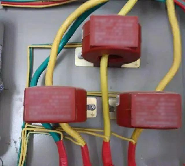
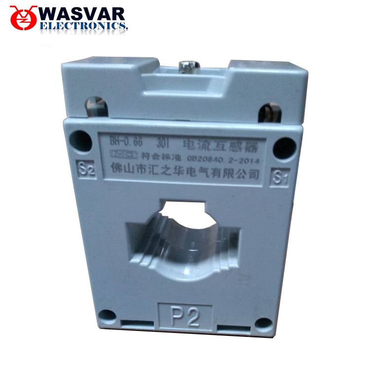
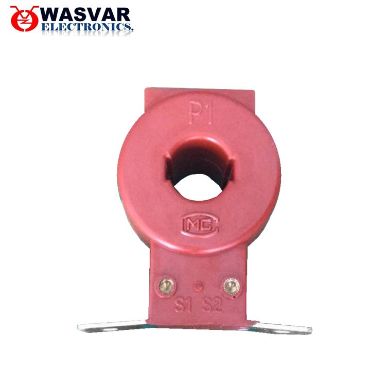
First select the appropriate current transformer, and then pass the cable through the current transformer. At this time, the current transformer will induce current from the cable, and the magnitude of the induced current is just reduced by a certain multiple. Send the induced current to the meter for measurement, and then multiply the measured result by a certain multiple to get the true result.
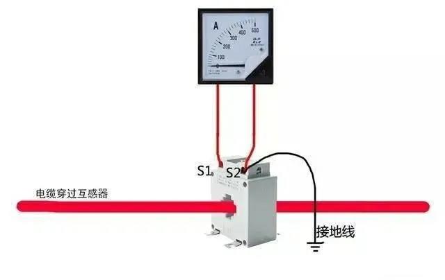
For example, now we need to measure the current of a cable. First put a cable through a 500/5 current transformer (500/5 is actually 100 times), and then connect the current transformer to the ammeter. The result of the ammeter is 4A. It can be calculated that the true current of the cable is 4*100=400A.
The wiring diagram is as follows:

Some readers may say that this can also be achieved with a clamp meter. In fact, there is a current transformer inside the clamp meter. The principle is similar.
Use
1) The wiring of the current transformer should follow the series principle: that is, the primary winding should be connected in series with the circuit under test, and the secondary winding should be connected in series with all instrument loads
2) According to the measured current, choose the appropriate change, otherwise the error will increase. At the same time, one end of the secondary side must be grounded to prevent the primary side high voltage from entering the secondary low voltage side when the insulation is damaged, causing personal and equipment accidents
3) No open circuit on the secondary side is allowed. Once the circuit is opened, the primary current I1 will all become the magnetizing current, causing φm and E2 to increase sharply, causing the core to be over-saturated and magnetized, causing serious heating and even burning the coil; at the same time, after the magnetic circuit is over-saturated and magnetized , Make the error increase. When the current transformer is working normally, the secondary side is similar to a short circuit. If it is suddenly opened, the excitation electromotive force will suddenly change from a small value to a large value, and the magnetic flux in the iron core will show a severely saturated flat top. Therefore, the secondary winding will induce a very high peak wave when the magnetic passes through zero, and its value can reach thousands or even tens of thousands of volts, which threatens the safety of workers and the insulation performance of instruments. In addition, an open circuit on the secondary side causes E2 to reach hundreds of volts, which will cause an electric shock if touched. Therefore, the secondary side of the current transformer is equipped with a short-circuit switch to prevent the primary side from opening. K0 in Figure 1, during use, once the secondary side is open, the circuit load should be removed immediately, and then stop processing. It can be reused after everything is handled.
4) In order to meet the needs of measuring instruments, relay protection, circuit breaker failure judgment and fault recording, etc., in the circuits of generators, transformers, outgoing wires, bus section circuit breakers, bus tie circuit breakers, bypass circuit breakers, etc. All are equipped with current transformers with 2-8 secondary windings. For large-current grounding systems, generally three-phase configuration; for low-current grounding systems, two-phase or three-phase configuration according to specific requirements
5) The installation location of the protective current transformer should be set as far as possible to eliminate the unprotected area of the main protective device. For example: if there are two sets of current transformers, and the location permits, they should be installed on both sides of the circuit breaker so that the circuit breaker is in the cross protection range
6) In order to prevent the bushing flashover of the pillar current transformer from causing a bus failure, the current transformer is usually arranged on the outlet or transformer side of the circuit breaker
7) In order to reduce the damage caused by the internal fault of the generator, the current transformer used for automatically adjusting the excitation device should be arranged on the outlet side of the generator stator winding. In order to facilitate analysis and find internal faults before the generator is incorporated into the system, the current transformer used for the measuring instrument should be installed on the neutral side of the generator.
principle
In the power supply lines, the difference in current and voltage varies from a few amperes to tens of thousands of amperes. In order to facilitate the measurement of the secondary instrument, it needs to be converted into a relatively uniform current. In addition, the voltage on the line is relatively high, such as direct measurement, which is very dangerous. The current transformer plays the role of current conversion and electrical isolation. Earlier, most of the display instruments were pointer-type current and voltmeters, so the secondary current of the current transformer was mostly ampere-level (such as 5A, etc.).
The current ratio between the primary winding current I1 of the current transformer and the secondary winding I2 is called the actual current ratio K. The current ratio of the current transformer when it works at the rated operating current is called the current transformer rated current ratio, which is represented by Kn.
Kn=I1n/I2n

What are the common faults of current transformers? How to judge the treatment? What items should be checked during normal patrol inspection.
A. Common faults of current transformers are:
1. Open circuit on the secondary side of current transformer
2. Overheating of the current transformer during operation
3. Smoke or foul smell inside the current transformer
4. The screw of the current transformer coil is loose, short circuit between turns or between layers
5. Discharge inside the current transformer, abnormal sound or discharge spark between the lead and the shell
6. Oil-filled current transformer has serious oil leakage or low oil level
B. Generally, judgment and treatment should be based on abnormal phenomena. For example, use the wax test piece to check the heating condition, and judge whether the circuit is open according to the sound and the indicator value of the meter. Once a fault is found, repair or replace it immediately. The items of normal patrol inspection generally include:
1. Check for overheating and abnormal smell
2. Regularly check the insulation
3. Check whether the three-phase indication value of the ammeter is within the allowable range and whether it is in overload operation
4. Whether the porcelain part is clean and complete, whether there is damage and discharge phenomenon
5. Whether the oil level of the oil-filled current transformer is normal and whether there is oil leakage

Why is the secondary side of the current transformer not allowed to open? What is the danger after opening the road?
1. Generally, the primary current of the current transformer has nothing to do with the secondary load current.
When the current transformer is operating normally, since the secondary side impedance is very small (close to the short-circuit state), most of the magnetic field lines generated by the primary current are compensated by the secondary current, the total magnetic flux density is not large, and the secondary side potential is not high. But when the secondary is open, the secondary current is equal to zero, and the primary current completely becomes the excitation current, which generates a high potential in the secondary coil (the peak value can reach several thousand volts or even higher), which may damage the secondary insulation , And it also threatens personal safety. In addition, an excessive increase in the magnetic flux density of the iron core may also cause the iron core to overheat and be damaged.
The hazards of long-term overload of current transformers
Once the current transformer is overloaded for a long time, it will cause the core magnetic flux density to reach saturation, increase the error of the current transformer, and the meter indication is incorrect, so it is difficult to grasp the actual load or operating conditions. In addition, due to the increase in magnetic flux density, the iron core and the secondary coil will overheat and the insulation will be damaged.
Symptoms and treatment of open circuit on the secondary side of the current transformer:
When the secondary side of the current transformer is open, the following phenomena are often accompanied:
1. The ammeter and power meter indicate zero, and the watt-hour meter does not turn and makes a buzzing sound.
2. The current transformer itself has squeaking discharge sound or other abnormal sounds, and the terminal block may be burnt.
When the current transformer is open, the level of potential generated is related to the magnitude of the primary current. Therefore, when dealing with the open circuit fault of the current transformer, the load must be reduced or the load must be zero, and then use insulating tools to deal with it, and the corresponding protection device should be disabled when dealing with it.


